Anhui Parker New Material Co.,Ltd
ISO9001      IATF16949

insulation blanket manufacturer

News

  • Silicone Coated Fiberglass Fabric for Expansion Joints: What Should Buyers Specify?
    Silicone Coated Fiberglass Fabric for Expansion Joints: What Should Buyers Specify? Oct 03, 2026
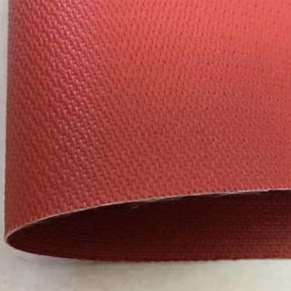
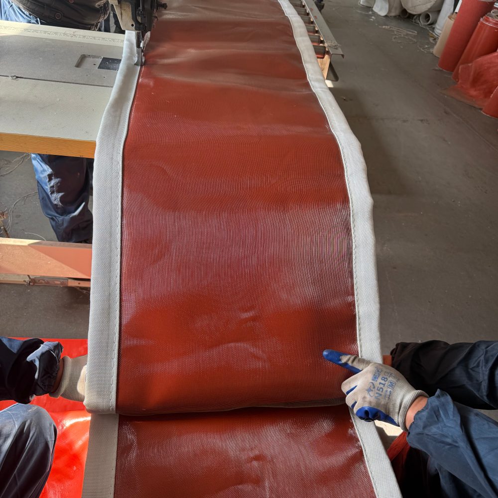
    Silicone coated fiberglass fabric for expansion joints should be specified by its position in the assembly, the temperature at that layer, the process medium, pressure conditions and movement requirements. Fabric thickness and coating sides belong in the specification, but neither can establish the performance of the finished joint. A request for "silicone fiberglass cloth for a hot duct" leaves several purchasing decisions unresolved. Is the buyer ordering roll material for fabrication, a replacement flexible belt or a complete connector? Will the silicone face contact the process gas, or will it form an external cover behind other protective layers? BSTFLEX supplies silicone coated fiberglass fabric for industrial fabrication and non-metallic fabric expansion joints for application-specific duct connections. Establishing the supply scope and operating conditions first makes the resulting quotations easier to compare. Start by Identifying the Fabric Layer Silicone coated fiberglass can be considered for suitable hot-air connectors and as an outer cover in a composite expansion joint. These are different duties. A material exposed directly to the air stream must meet that exposure, while an external cover must be selected for the conditions that actually reach it. Ask the designer to identify the proposed cloth on a cross-section drawing. Is it the flexible wall, an outer protective ply or part of a qualified sealing construction? An insulation layer reduces heat transfer; a chemical barrier protects against the medium; an outer cover addresses external exposure. Do not assume one coated cloth performs all three functions. For background on the substrate and coating, see What Is Silicone Coated Fiberglass Fabric and Where Is It Used? Keep Process Temperature and Fabric Temperature Separate Provide the normal gas temperature, design temperature and any short-duration excursion, including its duration and expected frequency. Separately identify the temperature expected at the silicone-coated layer. When that value is unknown, request a thermal review rather than assigning the gas temperature to every layer or assuming the outside remains cool. The selected grade's finished-fabric rating must govern its use. A temperature quoted for bare fiberglass does not establish the allowable temperature of the silicone coating, a fabricated seam or a complete expansion joint. Include ambient conditions, nearby radiant heat sources and the proposed insulation arrangement in the review. Do not add external insulation or an enclosing weather cover without the joint designer's approval: changing heat dissipation can change the temperature at the flexible element and its attachments. Describe the Medium, Including Startup and Shutdown Conditions Clean hot air and wet industrial flue gas are not interchangeable environments. Silicone's weather resistance should not be interpreted as general resistance to corrosive flue-gas constituents. A silicone outer cover may be...
    read more
  • Welding Blanket Size Guide: 6x6, 6x8, 8x8, 10x10, Grommets and Custom Sizes
    Welding Blanket Size Guide: 6x6, 6x8, 8x8, 10x10, Grommets and Custom Sizes Oct 03, 2026
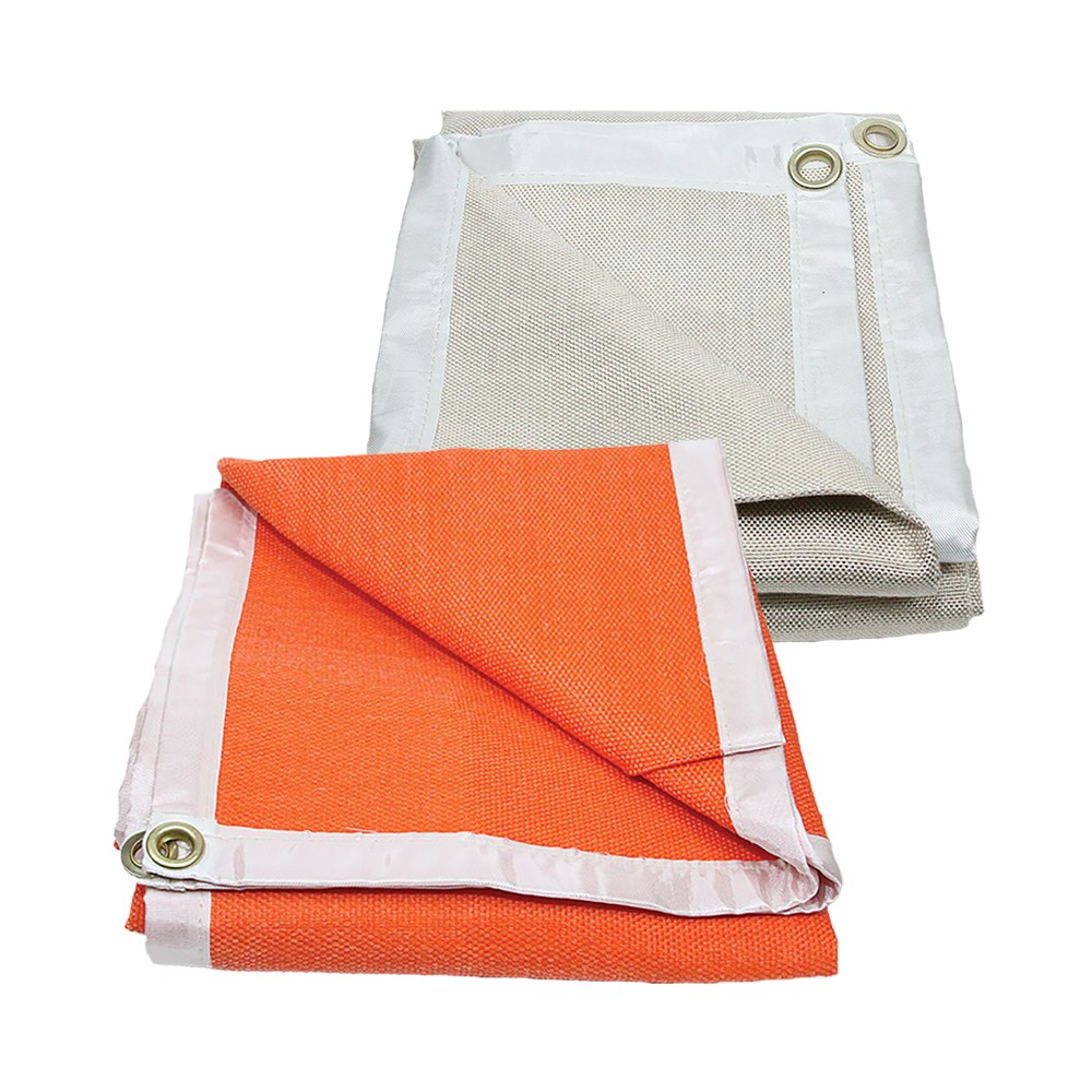
    A welding blanket can be large enough on a purchase order and still leave part of the equipment exposed after installation. Fabric used for side drops, overlaps and folds is no longer available to cover the main surface. Hems and seams can also make a nominal size different from the finished dimensions. This welding blanket size guide compares 6x6, 6x8, 8x8 and 10x10 ft formats, then explains how to specify the finished size and grommet layout for your installation. BSTFLEX manufactures industrial welding blankets in these dimensions and other custom sizes. The four sizes below are reference formats, not the limits of our manufacturing range. Send the dimensions your application requires rather than changing the installation to fit a short list of sizes. Welding Blanket Size Chart: 6x6, 6x8, 8x8 and 10x10 ft In this guide, 6x6 means 6 feet by 6 feet, not 6 inches or 6 meters. The metric figures below are exact conversions of the stated dimensions; they are not manufacturing tolerances or a guarantee of finished size for an unspecified product. Size Reference Dimensions in Inches Dimensions in Millimeters Flat Area 6x6 ft welding blanket 72 x 72 in 1828.8 x 1828.8 mm 36 sq ft 6x8 ft welding blanket 72 x 96 in 1828.8 x 2438.4 mm 48 sq ft 8x8 ft welding blanket 96 x 96 in 2438.4 x 2438.4 mm 64 sq ft 10x10 ft welding blanket 120 x 120 in 3048 x 3048 mm 100 sq ft Custom welding blanket Specify required width and length Manufactured to agreed dimensions Depends on the approved size A 1800 x 1800 mm blanket is not exactly the same size as a 6x6 ft blanket. Likewise, 3000 x 3000 mm is smaller than 10x10 ft. Use one controlling unit on the order and identify any converted dimensions as reference values. Choosing Between 6x6 and 6x8 A 6x8 welding blanket adds two feet in one direction compared with a 6x6 blanket. That extra length can be allocated to a longer covered surface or a greater hanging drop, depending on the layout. It does not increase both dimensions. For a rectangular hanging panel, mark which edge is the top. A panel measuring 6 ft wide by 8 ft high needs a different attachment layout from one installed 8 ft wide by 6 ft high, even though both use the same area of fabric. Choosing Between 8x8 and 10x10 An 8x8 welding blanket has 64 square feet of flat area; a 10x10 has 100 square feet. The larger format provides more material for coverage, but also increases fabric weight when the construction is otherwise identical. Before selecting the larger panel, check the available support, access for installation and how the blanket will be removed and stored. A larger size does not, by itself, provide a higher temperature rating or establish suitability for heavier spatter. Specify Finished Dimensions After Hemming Three measurements need to be kept separate: the fabric cut size, the finished blanket size and the coverage remaining after installation. Cut size is the material dimension before sewing. Finished size is the outside dimension after hems a...
    read more
  • Catalytic Converter Heat Shield Material: Sheet Selection for OEM Projects
    Catalytic Converter Heat Shield Material: Sheet Selection for OEM Projects Oct 02, 2026
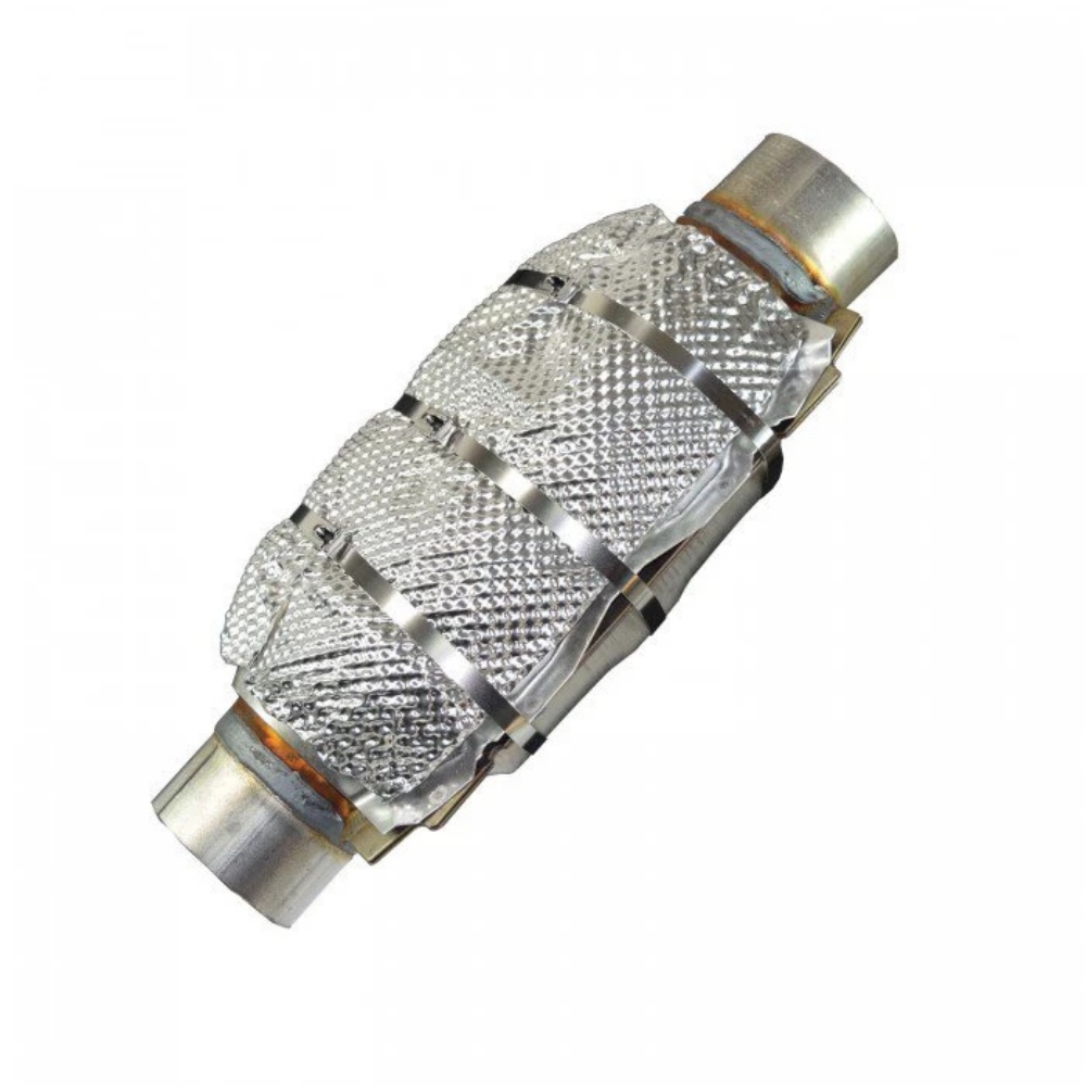
    Two suppliers can quote the same request for catalytic converter heat shield material and offer substantially different constructions. One may propose a thin metal cover shaped around the converter. Another may quote a broad underbody panel. A third may include insulation between metal facings. Comparing those quotations by material name and price alone leaves the main engineering requirement unresolved. Catalytic converter heat shield material forms an external thermal barrier between the hot exhaust assembly and nearby vehicle components. For a sheet-material purchase, first identify the barrier's position, attachment method and layer construction. Only then can alloy, thickness and embossed profile be specified meaningfully. This guide concerns metal sheet for thermal shielding. It does not cover the catalyst substrate, its internal support mat or theft-deterrent plates. Identify Which Part the Drawing Actually Requires The converter casing and its heat shield are not the same component. The casing encloses the catalyst assembly; an external heat shield manages heat exposure outside it. Walker's converter construction guide distinguishes the body, catalyst cushioning mat and external body and pipe heat shields. Component Function in the Assembly What the Sheet Supplier Needs to Know Converter casing Encloses the catalyst and forms part of the exhaust enclosure This is a casing-material inquiry, not an external heat shield sheet specification Exhaust-mounted heat shield Provides a thermal barrier close to the converter body or connecting exhaust section Local shape, attachment details, clearance and the shield's operating conditions Body-mounted underfloor shield Separates the exhaust heat source from the floor, tunnel or adjacent vehicle components Panel outline, vehicle-side mounting points and clearance throughout exhaust movement Metal-faced insulated shield Combines metallic layers with a specified insulating layer The complete layer stack, not just the visible outer metal Mark the heat-source side and vehicle-body side on the drawing. Include an assembly view: a flat outline alone cannot show which surface faces the converter or how the finished part is supported. The Converter Is More Than a Hot Section of Pipe Catalytic reactions can release heat as exhaust pollutants are converted. Walker describes this heat generation in its explanation of converter operation. A material specification copied from a nearby pipe shield therefore needs to be checked against the converter installation rather than accepted unchanged. For development, identify what the barrier must protect: a floor panel, a wiring connector, a fluid line or another assembly. Give each protected component an agreed temperature limit and measurement location. The objective is not merely to make the exposed face of the shield look intact after a test. Keep abnormal converter overheating separate from shield development. Engine faults, including misfires, can cause excessive co...
    read more
  • Plain vs Stitch-Bonded Silica Needle Mat: Which Construction Fits Your Assembly?
    Plain vs Stitch-Bonded Silica Needle Mat: Which Construction Fits Your Assembly? Oct 02, 2026
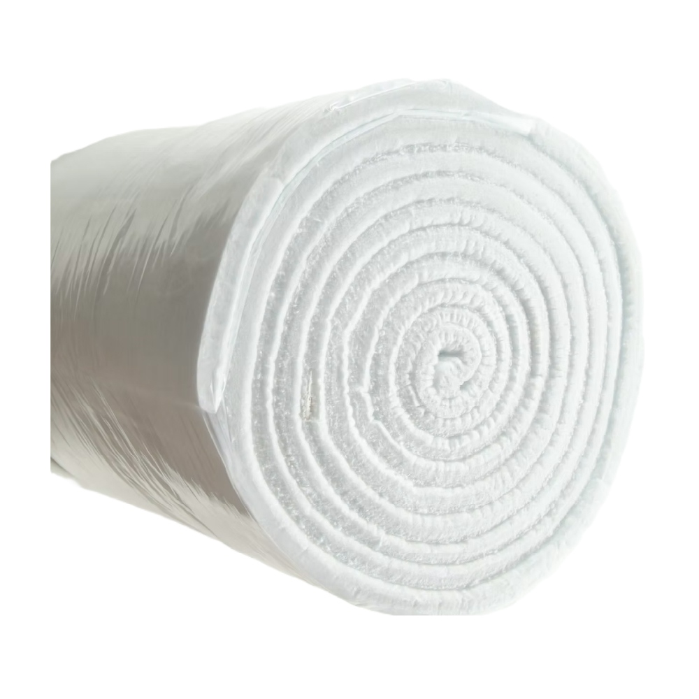
    A silica insulation core can meet the thermal requirement and still be difficult to cut, position or refit. That is where the choice between plain and stitch-bonded silica needle mat becomes important: the decision concerns how the material behaves during fabrication and service, not simply how much heat the fiber can withstand. Consider plain silica needle mat when the assembly supports the insulation and samples meet the handling requirements. Evaluate stitch-bonded silica needle mat when the project needs additional mechanical integrity during cutting, installation or repeated maintenance. Neither choice removes the need to verify the fiber grade, installed thickness and complete assembly. What Changes When Silica Needle Mat Is Stitch-Bonded? Plain silica needle mat is a nonwoven material in which needle punching mechanically interlocks the fibers. In this comparison, plain means that the mat has no additional stitch-bonded reinforcement. It does not mean that the fibers are loose or that the material has no mechanical strength. The BSTFLEX plain silica needle mat is the starting point for this construction. A stitch-bonded version adds a reinforcing thread system to the needled mat. The purpose is to improve mechanical integrity, such as resistance to pulling or separation during handling. The BSTFLEX stitch-bonded silica needle mat provides a separate option for projects specifying this additional structure. The benefit must be assessed for the actual mat and thread combination, rather than inferred from the word reinforced. Both remain nonwoven insulation mats. Stitch bonding does not turn the core into woven silica fabric, and it is not the same as sewing a finished jacket around an insulation layer. Start With the Assembly: Three Different Decisions A Supported Insulation Layer Inside a Panel For a mat enclosed between supporting surfaces and rarely disturbed after installation, begin by evaluating the plain construction. Check whether a cut piece stays positioned during fitting and whether the enclosure retains it without unacceptable gaps or compression. If the plain mat meets those requirements, additional stitching needs a specific justification. Do not reject an otherwise suitable plain mat solely because another quotation includes reinforcement. Ask what the extra structure improves in this particular panel. A Removable Cover That Is Opened for Maintenance For removable insulation jackets, ask what happens to the core when the cover is lifted, folded back and refitted. Trial both constructions when the design exposes the insulation to repeated handling. Inspect for local thinning, separation or movement inside the facing rather than judging only the appearance of an unused roll. Stitch bonding is worth evaluating if handling trials reveal a weakness that reinforcement could address. The cover still needs suitable facings, seams and retention. A stronger core does not correct an unsupported section or a closure that compresses the in...
    read more
  • Fabric Expansion Joints for Steel Mills and Furnace Exhaust Ducts
    Fabric Expansion Joints for Steel Mills and Furnace Exhaust Ducts Oct 01, 2026
    A fabric expansion joint for a steel mill must be specified for its exact position in the exhaust system. A connection near a furnace, a cooled extraction duct and a fan inlet may belong to the same process line, but they do not necessarily experience the same temperature, pressure, dust loading or movement. Fabric expansion joints provide flexible connections in suitable low-pressure gas ducts. They accommodate specified thermal growth and equipment displacement while maintaining the required gas seal. In furnace exhaust service, the flexible belt, insulation, attachments and internal protection must work together as an assembly. BSTFLEX manufactures custom non metallic fabric expansion joints for industrial ducting, hot-air, exhaust and flue-gas applications. Round, rectangular and project-specific configurations can be evaluated from customer drawings and operating data. Where Fabric Expansion Joints Fit in Steel Plant Ductwork The equipment name is the starting point, not the complete specification. Identify the connection on the plant drawing and explain what reaches it during normal operation, startup, shutdown and credible upset conditions. Duct Location Conditions to Establish Design Focus Electric arc furnace extraction system Exact location relative to cooling, dilution and dust-removal equipment Confirm whether fabric construction is suitable at the proposed connection Ladle furnace fume-extraction duct Gas temperature, intermittent operation, dust and equipment movement Match the joint to the stationary duct connection and specified movement Reheating or heat-treatment furnace exhaust Local exhaust temperature, operating cycle and external heat exposure Thermal protection and repeated movement Dust-collection and baghouse ductwork Dirty-side or clean-side location, pressure and particulate conditions Sealing, abrasion protection and pressure-related deformation Fan inlet or outlet Pressure fluctuations, vibration and available installation space Control of belt flutter and clearance throughout movement Waste-heat recovery duct Connection temperature, equipment growth and process changes Compatibility between the joint and adjoining equipment Electric Arc Furnace Exhaust Requires a Location-Specific Review An electric arc furnace dedusting system can include water-cooled primary ducts, additional gas cooling, secondary fume extraction, filtration and induced-draft fans. These sections perform different functions and should not receive one generic expansion joint specification. A fabric connector is not an automatic replacement for a water-cooled duct, a sliding connection or another component designed for direct furnace off-gas. The system designer must approve the proposed installation point and operating limits. The furnace process temperature is not a substitute for the measured or calculated gas temperature at that connection. Likewise, a stationary duct expansion joint should not be assumed to accommodate furnace tilting, roof lif...
    read more
first page 1 2 3 ... 82 last page
[  a total of  82  pages]
leave a message

leave a message

    If you have questions or suggestions, please leave us a message,we will reply you as soon as we can!

Home

Products

About

Contact

top