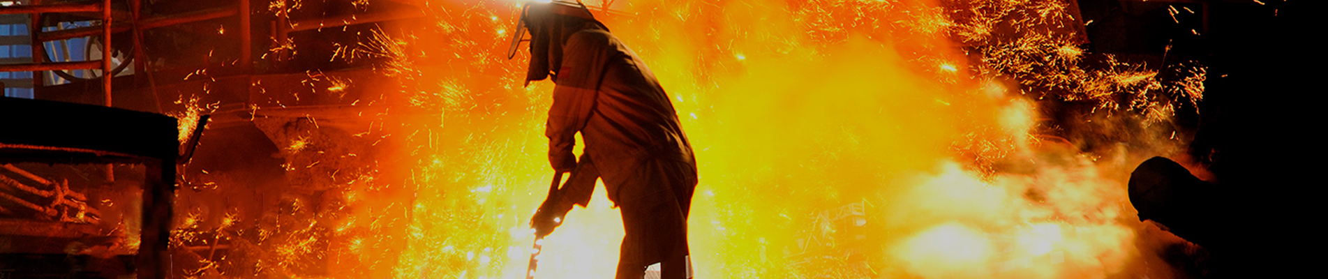
Power plant flue gas ductwork operates under a combination of high temperature, thermal movement, vibration, pressure fluctuations, corrosion and particulate loading. Large duct sections can expand, contract and shift during startup, normal operation and shutdown. A properly engineered fabric expansion joint provides a flexible connection that absorbs this movement while maintaining the required separation and sealing between adjoining duct sections.
Unlike a simple flexible connector, a power plant expansion joint must be designed around the actual flue gas conditions. Temperature, pressure, gas composition, fly ash, movement, duct dimensions and liner configuration all influence the construction of the joint.
BSTFLEX manufactures custom non metallic fabric expansion joints for large industrial duct systems, including boiler, flue gas, air pollution control and exhaust applications.
| Parameter | Why It Matters |
|---|---|
| Operating Temperature | Determines the thermal protection and flexible material system |
| Maximum Temperature | Accounts for startup, upset and transient conditions |
| Pressure | Determines belt loading and movement behavior |
| Flue Gas Composition | Influences chemical compatibility and sealing material selection |
| Moisture | Important for condensation and acid-dew-point conditions |
| Fly Ash and Dust | May require an internal liner or abrasion protection |
| Axial Movement | Determines compression and extension capability |
| Lateral Movement | Determines required flexible geometry |
| Duct Dimensions | Influences frame, corner and belt construction |
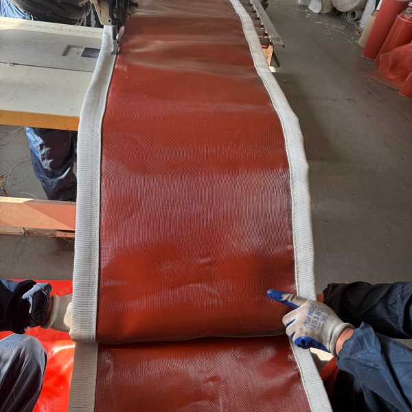
Flue gas ducts are connected to equipment that operates through significant temperature changes. A duct that is several meters long can experience measurable dimensional growth when heated.
The problem is not limited to the duct itself. Thermal movement can also occur between:
These components do not necessarily expand in exactly the same direction or at the same rate.
A flexible joint provides a controlled location where relative movement can occur without forcing the entire duct system to absorb the displacement as mechanical stress.
A power plant fabric expansion joint can be installed at multiple locations throughout a flue gas handling system.
Typical locations include:
The operating conditions can vary significantly between these locations, so one material construction should not automatically be applied throughout the plant.
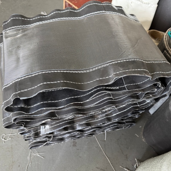
Boiler-related ductwork can experience substantial thermal cycling.
During startup, the duct temperature rises from ambient conditions toward operating temperature. During shutdown, the process reverses. This repeated thermal expansion and contraction can produce thousands of movement cycles during the service life of the equipment.
A boiler duct expansion joint therefore needs to accommodate repeated movement rather than only one maximum displacement event.
Important considerations include:
Air preheater connections can create demanding conditions because the gas temperatures and flow paths change across the equipment.
Expansion joints may be exposed to thermal movement, vibration and pressure differences while also operating near equipment with substantial structural mass.
The flexible joint must therefore allow the required movement without creating excessive reaction forces on the connected ductwork.
Induced draft fans are another common location for flexible connections.
Here the primary concern may be vibration and mechanical isolation rather than extreme temperature alone.
A fabric expansion joint at an ID fan connection can help accommodate:
The correct construction depends on whether the joint is located on the hot gas side, clean gas side or another section of the system.
Flue gas desulfurization systems can introduce a different set of challenges.
Wet flue gas can contain chemically aggressive components, and condensation may occur when the gas temperature falls below the acid dew point.
In these locations, the flexible material must be evaluated for:
A PTFE-based flexible barrier may be considered when chemical resistance is a major design requirement.
For a detailed material comparison, see our guide to Fabric Expansion Joint Materials: PTFE, Silicone, Fiberglass and Silica.
Flue gas is not simply hot air.
Depending on the fuel and pollution-control process, it may contain combinations of:
After gas cleaning and cooling, condensation can become an additional concern.
Consequently, a material that performs well in a dry hot-air duct may not be appropriate for a wet corrosive flue gas application.
Acid dew point conditions deserve special attention in flue gas systems.
When the gas cools sufficiently, certain components can condense and create highly corrosive liquids on internal surfaces.
This means the design temperature of a flexible sealing layer should not be based only on the maximum gas temperature.
The complete operating envelope should include:
Where wet acidic service is expected, chemical compatibility becomes a major part of fabric selection.
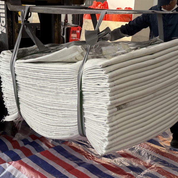
A common mistake is to select a high temperature fabric expansion joint simply by choosing the fabric with the highest advertised temperature rating.
That approach can produce an unsuitable joint.
A high-temperature textile may tolerate direct heat extremely well but provide limited chemical resistance or gas sealing capability. Conversely, a chemically resistant PTFE layer may not be intended for direct exposure to the hottest portion of the flue gas.
Modern fabric expansion joints therefore frequently use multiple functional layers.
A high-temperature flue gas joint may use a combination of materials, with each layer performing a specific function.
Typical Functional Arrangement
Flue Gas
↓
Internal Flow / Abrasion Protection
↓
High Temperature Fabric
↓
Insulation
↓
Fiberglass Reinforcement
↓
PTFE or Other Gas-Sealing Barrier
↓
External Protection
This is an engineering concept rather than a universal construction. Actual material selection and layer sequence depend on the operating conditions of the specific power plant.
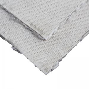
Silica fabric can be considered for locations where the hot-face temperature is beyond the practical range of conventional fiberglass materials.
Its primary role in a composite expansion joint is generally thermal protection rather than acting as the sole gas-sealing membrane.
BSTFLEX supplies 96% high-temperature silica fabric for demanding thermal-protection applications.
In a power plant expansion joint, silica fabric can be incorporated into a multilayer system when the hot side requires additional thermal protection.
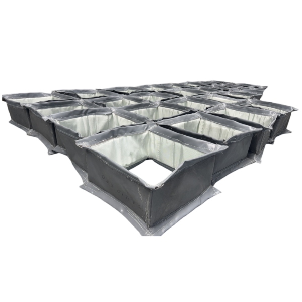
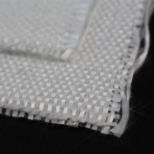
Fiberglass is widely used in industrial fabric expansion joints because it provides a useful combination of strength, dimensional stability and temperature resistance.
It can serve as:
Fiberglass does not necessarily have to be the outermost layer. Its position depends on the function required from the complete joint.
PTFE-coated fiberglass can be useful when the joint requires a chemically resistant flexible barrier.
Its potential advantages include:
However, the PTFE layer must be protected from temperatures beyond its suitable operating range.
In a high-temperature system, this can be achieved through insulation and hot-side protective layers.
Silicone-coated fiberglass may be appropriate in locations where flexibility, weather resistance and moderate high-temperature performance are important.
It can be particularly useful on the outer side of a composite construction or in relatively moderate-temperature sections of the flue gas system.
It should not automatically be specified for the hottest portion of a boiler outlet duct without evaluating the actual layer temperature.
A fabric expansion joint should not necessarily be exposed directly to the full velocity of the flue gas.
An internal liner can be used to redirect the gas flow and protect the flexible assembly.
Depending on the system, the liner can help reduce:
For particulate-laden gas, liner design is one of the most important components of the complete expansion joint assembly.
Coal-fired and other particulate-producing power plants can expose duct expansion joints to fly ash.
High gas velocity can turn relatively fine particles into an effective abrasive stream.
If these particles directly impact the flexible belt, wear can occur much faster than expected from temperature exposure alone.
For this reason, the design should consider:
Many power plant flue gas systems operate under negative pressure because of induced draft fans.
Negative pressure can pull the flexible fabric inward.
This is particularly important for large rectangular expansion joints with long unsupported spans.
The design should therefore account for:
Providing the actual pressure value is much more useful than simply stating “vacuum service.”
Most large flue gas ducts are rectangular or square.
This creates additional engineering considerations compared with circular joints.
The four corners must transition smoothly between adjacent sides, while the long sides may experience greater deformation under pressure.
A rectangular fabric expansion joint should therefore be designed around the complete perimeter.
Important dimensions include:
| Dimension | Required Information |
|---|---|
| Width | Actual duct width |
| Height | Actual duct height |
| Face-to-Face | Distance between attachment planes |
| Flange | Width, thickness and attachment configuration |
| Corner | Actual corner geometry and radius where applicable |
For large replacement joints, photographs and dimensional drawings are strongly recommended.
Thermal expansion generally produces axial movement as connected duct sections change length.
The expansion joint should be specified with separate values for compression and extension.
For example:
Axial compression: 40 mm
Axial extension: 15 mm
This is more useful for engineering than specifying only the total theoretical thermal growth.
Power plant equipment can move relative to the surrounding structure.
Lateral displacement may result from:
The fabric expansion joint should be designed to absorb the required displacement without excessive fabric strain or contact between internal components.
A power plant expansion joint can experience repeated thermal cycles throughout its service life.
Every startup and shutdown can produce another movement cycle.
This means service life depends not only on the maximum temperature but also on:
A joint designed for one large movement event is not necessarily optimized for thousands of smaller thermal cycles.
When a fabric joint fails prematurely, the visible damage is not always the original cause.
Common failure mechanisms can include:
Replacing the fabric with a higher-temperature material without identifying the failure mechanism may not solve the underlying problem.
For rectangular joints, corners are important inspection points.
Look for:
Damage concentrated around one corner can indicate movement, installation or geometry problems rather than a simple material-temperature issue.
The internal liner should also be inspected.
Check for:
A damaged liner can expose the flexible belt to conditions for which it was never designed.
For replacement projects, copying the dimensions of the old fabric belt is not always sufficient.
The replacement should be reviewed against the current operating conditions.
Before ordering, collect:
If the old joint failed early, include photographs showing the damaged areas.
For a custom flue gas expansion joint, the most useful information is the actual operating envelope.
| Information | Example |
|---|---|
| Duct Size | 3000 × 2500 mm |
| Face-to-Face | 250 mm |
| Normal Temperature | 350°C |
| Maximum Temperature | 450°C |
| Pressure | -5 kPa |
| Process Gas | Flue gas |
| Axial Movement | ±30 mm |
| Lateral Movement | ±25 mm |
| Gas Velocity | Project-specific |
| Particulate Loading | Fly ash / dust conditions |
The values above are examples only. Actual project specifications must be used for engineering.
Power plant duct systems are rarely identical.
Two joints may have the same nominal dimensions but completely different operating conditions.
One may operate with dry hot gas, while another handles wet corrosive flue gas. One may experience positive pressure, while another operates under substantial negative pressure. One may require an abrasion-resistant liner, while another does not.
For this reason, a non metallic expansion joint should be specified as an engineered assembly rather than selected only by size.
| Material | Potential Role | Typical Selection Driver |
|---|---|---|
| Fiberglass | Reinforcement | Strength and thermal stability |
| Silicone-Coated Fiberglass | Flexible external or sealing layer | Flexibility and environmental resistance |
| PTFE-Coated Fiberglass | Chemical-resistant barrier | Corrosive or wet gas |
| Silica Fabric | Hot-face protection | Severe thermal exposure |
| Insulation | Thermal barrier | Protecting lower-temperature layers |
| Metal Liner | Flow and abrasion protection | High velocity or particulate gas |
Both fabric and metallic expansion joints can be used in industrial duct systems, but their characteristics are different.
| Factor | Fabric Expansion Joint | Metal Expansion Joint |
|---|---|---|
| Flexible Element | Technical fabric composite | Formed metal bellows |
| Large Duct Sizes | Highly suitable | Design dependent |
| Lateral Flexibility | Generally high | Configuration dependent |
| Thermal Insulation | Can be integrated into multilayer construction | Usually requires separate thermal design |
| Chemical Barrier | Can use PTFE-based layers | Depends on alloy selection |
| Low Reaction Force | Strong advantage in many duct applications | Spring force must be considered |
| Replacement | Flexible belt may be replaceable | Assembly-specific |
The better choice depends on pressure, temperature, movement, gas chemistry, duct geometry and the requirements of the complete system.
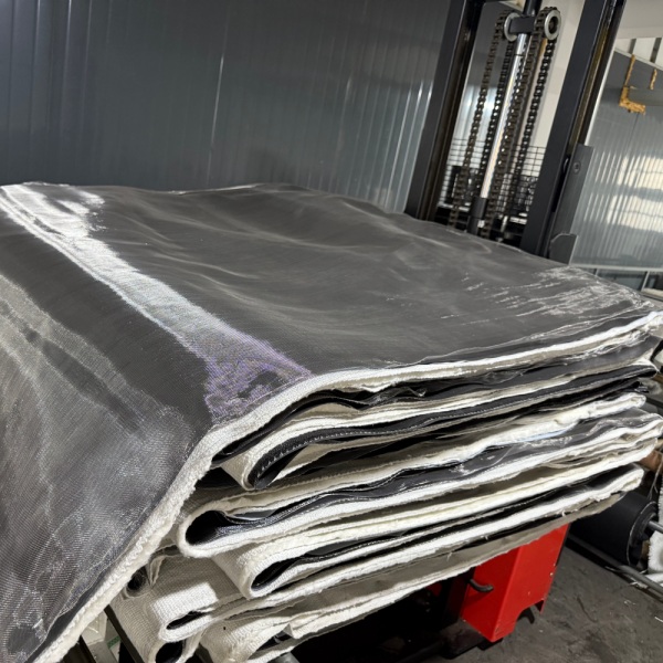
A useful specification should describe the complete service condition rather than simply stating:
“High temperature fabric expansion joint.”
A stronger specification identifies:
This information allows the manufacturer to engineer the flexible assembly around the actual application.
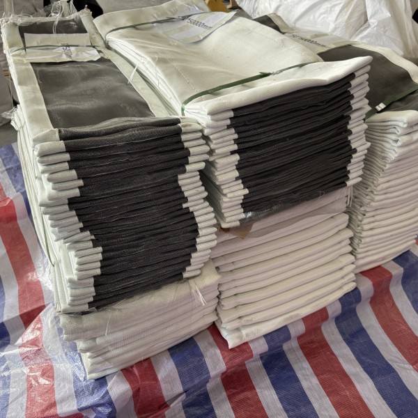
BSTFLEX develops custom fabric expansion joints for power plant flue gas systems according to the dimensions and operating conditions supplied by the customer.
Depending on the application, the construction can incorporate fiberglass reinforcement, silicone-coated fabrics, PTFE-based gas barriers, silica high-temperature fabric, insulation and internal flow or abrasion protection.
Custom configurations are available for rectangular, square, round and non-standard duct geometries.
For the complete product specification, visit the Non Metallic Fabric Expansion Joint product page.
Send BSTFLEX your duct dimensions, face-to-face length, operating and maximum temperature, pressure, flue gas composition, movement, gas velocity, particulate conditions and existing liner details.
For replacement projects, include photographs and drawings of the existing installation whenever possible.

 français
 Deutsch
 русский
 italiano
 español
 português
 Nederlands
 العربية
 日本語
日本語 한국의
한국의 Türkçe
 Polski
 Tiếng Việt
 slovenský
 Indonesia