français
 Deutsch
 русский
 italiano
 español
 português
 Nederlands
 العربية
 日本語
日本語 한국의
한국의 Türkçe
 Polski
 Tiếng Việt
 slovenský
 Indonesia




Replacement fabric expansion joints must match both the existing connection and the current operating requirements. To specify one, identify the replacement scope, measure the attachment geometry in a documented plant condition, and provide temperature, pressure, gas composition and movement data. The dimensions of a worn fabric belt are useful evidence, but they are not automatically the correct manufacturing dimensions for its replacement.
BSTFLEX supports replacement projects with custom non metallic fabric expansion joints for industrial ducting, flue gas, exhaust and hot-air systems. This guide explains how to prepare the survey information needed for an engineering review and quotation.
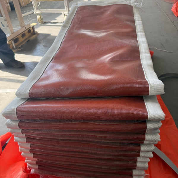
Define What Is Being Replaced
Before measuring, agree on the supply boundary. A request for a “replacement expansion joint” can describe several different packages.
- Flexible belt only
- The existing frames and attachment hardware are intended to remain. The survey must establish their dimensions and condition, together with the required belt construction and closure arrangement.
- Flexible belt with internal components
- The scope also includes items such as insulation pillows, accumulation barriers or sealing accessories. Identify each component separately rather than assuming it is included with the outer belt.
- Complete expansion joint assembly
- Frames, flexible elements, liners and attachment components are reviewed as an assembly. Measure the interfaces to the retained ductwork and confirm which welding or bolting connections will be disturbed.
Ask the quotation to identify included parts, excluded parts and items proposed for reuse. This avoids receiving a correctly manufactured belt while discovering during the outage that damaged hardware also needs replacement.
Establish a Safe Measurement Reference
Before hands-on inspection: Have authorized site personnel shut down and isolate the system, relieve stored pressure, and verify safe temperatures and access conditions. Apply the site's energy-isolation, permit-to-work and confined-space procedures where applicable. Confirm that the ductwork and connected equipment are adequately supported before disassembly. Do not loosen clamps or remove the joint on an operating duct.
Start with the equipment tag, original drawing, previous purchase specification and any modification records. Give every joint a separate identification number, even when several units appear identical.
Record the plant condition during the survey: cooled shutdown, residual warmth, temporary support arrangement or another documented condition. A measurement taken during an outage does not, by itself, establish the specified cold installation position.
Mark upstream and downstream ends, flow direction, top position and the viewing direction used on the sketch. For example, define left and right while looking downstream. Use the same orientation for measurements and photographs.
Keep the as-found measurements separate from the approved installation dimensions. Differences require review; they should not be silently corrected on a purchase order.
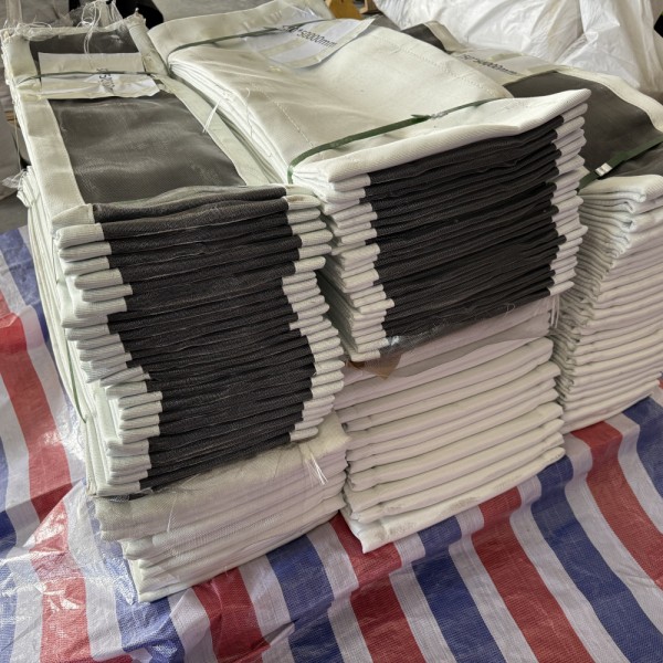
Record the Dimensions That Control Fit
The most important distinction is between the installed assembly geometry and the developed dimensions of the flexible material. Face-to-face distance, unclamped fabric length and total belt width describe different features.
| Dimension | What to record | Mistake to avoid |
|---|---|---|
| Duct opening | Internal width and height, or diameter, at each identified end. | Substituting an outside frame dimension for the flow opening. |
| Attachment geometry | Mounting surfaces, flange orientation, corner details and the perimeter by the belt. | Assuming the belt mounting perimeter equals the duct's internal perimeter. |
| Installed connection distance | Axial separation between identified reference planes; show the measurement endpoints in a section view. | Using “face-to-face” without identifying the surfaces measured. |
| Unclamped fabric length | The fabric portion outside the clamping zones, where safely accessible. | Confusing the fabric's developed path with a straight gap measurement. |
| Developed belt width | Edge-to-edge width across the removed belt, with its condition and measurement method recorded. | Using the installed gap as the total replacement belt width. |
| Perimeter and closure | Attachment perimeter, existing closure location and accessible joining area. | Adding an arbitrary splice allowance to obtain an order length. |
| Flange and hole pattern | Flange width and thickness, hole diameter, hole coordinates or pitch, quantity and orientation. | Assuming both ends have identical drilling. |
The replacement manufacturer should determine the finished belt dimensions from the approved geometry, clamping requirements, movement and construction. Do not apply a universal rule such as “installed gap plus 100 mm.”
Rectangular Joints: Survey Both Ends
At each connection, record the top and bottom widths, left and right heights, and both diagonals where accessible. Identify whether the readings refer to the opening, mounting surface or bolt pattern. Capture corner radii or other corner details rather than drawing every corner as a sharp right angle.
Measure the connection distance at several labelled positions around the perimeter. Retain individual readings so the reviewer can identify possible non-parallel faces, distortion or inconsistent measurement references.
For additional geometry considerations, see Rectangular Fabric Expansion Joints for Industrial Ductwork.
Round Joints: Identify the Diameter and Clocking
State whether each diameter is the duct inside diameter, mounting diameter, flange outside diameter or bolt-circle diameter. Measure in more than one direction when checking an existing opening for out-of-roundness.
Record the hole count and the angular position of the pattern relative to an agreed reference, such as the top of the duct. A matching bolt circle does not guarantee that two patterns have matching orientation.
Bolt Patterns: Use a Defined Datum
Measure hole locations from a clearly marked reference. On rectangular flanges, include the first-hole offset, corner arrangement and any changes in pitch. Note slots, enlarged holes and previous repairs.
Record both ends independently. Confirm whether the replacement belt will be supplied pre-punched or whether an approved site-punching procedure is required for the selected construction.
Example: do not order from an average alone. Suppose four connection-distance readings are 240, 244, 248 and 242 mm. Reporting only the 243.5 mm average removes information about the actual interface. Submit all four readings and their locations. These illustrative numbers are not acceptable installation tolerances or a replacement specification.
Separate Cold Offset From Working Movement
A replacement fabric expansion joint must accommodate the specified operating movement from an agreed installation reference. A sideways offset visible during shutdown is not automatically the required lateral movement rating.
Ask the plant engineer to distinguish an intentional cold preset from unintended misalignment. Do not force a deliberately preset connection into a visually centered position, and do not assume an unexpected offset can be absorbed without affecting the design.
Provide axial compression and extension separately, together with horizontal and vertical lateral movement and angular movement about identified axes. State which movements occur simultaneously. Report any known torsion, vibration amplitude, frequency or pressure pulsation for separate assessment.
Where movement data is unavailable, mark it as unknown. The existing belt's looseness, folds or apparent stretch cannot establish its remaining movement allowance.
Inspect the Components That Will Remain
A belt-only replacement depends on suitable retained metalwork. During the authorized shutdown inspection, record corrosion, distorted frames, damaged welds, uneven sealing surfaces and sharp edges. Check clamping bars and fasteners for damage rather than assuming they can be reused.
Photograph liners, their attachment points, overlap and available clearance. The engineering review must consider clearance throughout the specified movement, not just at the position seen during the survey. Contact marks can help identify locations needing closer investigation.
Record the condition and attachment of insulation pillows and accumulation barriers. Photograph displaced insulation, deposits and exposed areas before approved cleaning. Do not remove an internal component from the replacement scope merely because it is difficult to identify.
Also document external insulation or weather covers around the joint. Changes to the thermal arrangement should be reviewed with the replacement supplier rather than treated as a cosmetic maintenance choice.
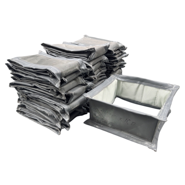
Use the Old Belt as Evidence, Not the Only Specification
An old belt can help identify attachment marks, closure details and the previous construction. However, deformation, damaged edges or deterioration may make its dimensions unreliable as a manufacturing template.
Record its measured dimensions as “removed component, as found.” Do not pull a damaged belt tight simply to produce a convenient width or length. Where a sample is requested, disclose process contamination and agree on safe preparation and shipping before dispatch.
Provide the installation date, approximate service duration, reason for replacement and any recent process changes. Include photographs showing the entire joint, its tag, attachments, closure and each damaged area with a scale reference where safe.
Describe observations without assuming a diagnosis. “Tear beside the upstream clamp” is more useful than “fabric too weak.” A photograph of discoloration does not prove that temperature caused the failure.
Changes in fuel, gas chemistry, moisture, dust loading, temperature or fan operation should be declared. A replacement that matches the former dimensions may still require a different material or protective arrangement.
Choose the Delivery Form Before Ordering
- Closed-loop flexible element
- Confirm that there is a practical installation route around the existing equipment. A factory-closed element is not automatically installable where both duct ends remain fixed.
- Open belt for site closure
- Confirm that the selected construction permits a site joint. Agree on the closure location, access, method, materials and personnel requirements with the manufacturer. Splice details are construction-specific.
- Complete or sectional assembly
- Check access openings, lifting restrictions, maximum transport dimensions and the proposed installation sequence. State which assembly work is expected at the factory and which is assigned to the site contractor.
For every delivery form, agree on hole preparation, gaskets or sealing accessories, component identification and installation instructions. There is no universal splice overlap, bolt torque or field-drilling method suitable for every fabric expansion joint.
A Replacement RFQ You Can Copy
Use one record per equipment tag. Attach the dimensioned sketch and original drawing where available. Write “unknown” beside missing information instead of entering zero or assuming that the previous material remains suitable.
Project identification:
Plant / equipment / joint tag / quantity / reason for replacement.
Requested scope:
Belt only / belt with internal components / complete assembly. List included items and components proposed for reuse.
Survey reference:
Date / plant condition / temperature at survey if known / viewing direction / upstream and downstream identification / temporary supports or modifications.
Connection details:
Opening dimensions / attachment dimensions / labelled connection-distance readings / corner details / flange thickness / hole pattern at both ends.
Movement requirement:
Approved cold position and preset / axial compression and extension / lateral movement in both directions / angular movement / simultaneous movements / vibration or torsion requiring review.
Operating conditions:
Normal temperature / design and excursion conditions with duration / operating and design pressure, including sign and units / pressure transients.
Process medium:
Gas composition / moisture and condensate / dust or solids / gas velocity / cleaning exposure / required sealing performance.
Existing construction:
Available material records / liner / insulation / accumulation barrier / clamping system / external insulation or cover / photographs and failure history.
Installation and delivery:
Open or closed element / access restrictions / site closure requirements / hole preparation / required delivery date / planned outage window / delivery destination.
Approval documents:
Drawing number and revision / measurement record / unresolved dimensions / requested inspection documents / person responsible for technical approval.
Approve the Drawing Before Fabrication
The survey describes what exists. The approved replacement drawing defines what will be manufactured and the conditions it must accommodate.
Resolve any differences between the original drawing and field measurements. Confirm connection dimensions, finished flexible-element geometry, hole preparation, closure position, material construction, movement reference and supply scope. Agree on tolerances and any site-dependent dimensions before releasing production.
On receipt, check identification and supplied components against the approved documents before the outage begins. Installation should follow the joint-specific instructions, including clamping, sealing, insulation and clearance requirements.
Questions That Commonly Delay Replacement Orders
- Can a replacement be evaluated without the original drawing?
- Yes. A dimensioned survey, photographs and operating information can support an initial review. Missing movement or material information may still need engineering confirmation before manufacture.
- Can only the fabric belt be replaced?
- Potentially, provided the retained frames, attachment components and internal protection remain suitable. Inspection and the agreed scope determine whether a belt-only replacement is appropriate.
- Will a wider belt solve repeated tearing?
- Not necessarily. More material does not establish the cause of tearing or verify clearance. Review the attachment geometry, movement, temperature and contact evidence before changing the belt dimensions.
Send BSTFLEX Your Replacement Joint Details
BSTFLEX manufactures non metallic fabric expansion joints in round, rectangular and custom configurations. Replacement requirements can be evaluated from available drawings, dimensional records and operating conditions.
Send the joint tag, survey sketch, photographs, requested supply scope and required delivery date. Include temperature, pressure, gas composition and movement data so the quotation addresses the application rather than dimensions alone.