order(moq):
1A steam moisture separator removes entrained liquid from a moving steam stream and directs the separated condensate toward a drain connection. The vessel may include inlet and outlet nozzles, a bottom drain, a steam trap connection, gauges, vents, supports and inspection points. Those features make a generic pipe wrap unsuitable for the complete assembly.
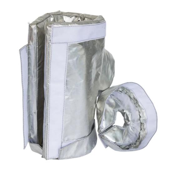
BSTFLEX manufactures removable steam separator insulation jackets to the actual equipment drawing or field dimensions. The jacket is divided into practical sections that follow the separator body and heads without blocking condensate drainage or routine inspection. Each section can be removed for maintenance and reinstalled without rebuilding the surrounding pipe insulation.
| Design area | Jacket arrangement | Required project information |
|---|---|---|
| Separator body | One-piece wrap or several numbered shell panels | Diameter, straight length, orientation and surface temperature |
| Upper and lower heads | Contoured end sections with suitable overlaps | Head shape, depth, nozzles and support details |
| Inlet and outlet | Fitted collars or transitions to adjacent pipe insulation | Nozzle size, flange dimensions and pipe-insulation thickness |
| Drain and trap connection | Exposed outlet, reinforced opening or separate collar | Drain size, valve or trap layout and operating clearance |
| Instruments and access points | Cutouts, removable flaps or independent small covers | Gauge, vent, nameplate and inspection-access requirements |
Wet steam can carry suspended droplets through the distribution system. A properly selected separator changes the flow path or uses centrifugal action so that liquid separates from the steam and collects at the drain. The condensate then has to leave through a correctly arranged drainage system.
The insulation jacket is an external thermal component. It can help reduce heat leaving the separator surface, but it does not perform the separation function and does not correct an undersized separator, blocked drain or failed steam trap. Separator sizing, installation direction and drainage remain the responsibility of the steam-system designer.
Vertical separators commonly have a cylindrical body with top, side or tangential connections and a drain at the lower point. A removable cover may use a shell wrap, a shaped upper-head panel and a lower section that terminates around the drain. Supports, lifting lugs and instrument connections are incorporated into the pattern.
The lowest area requires special attention. The blanket must not form a pocket that traps leaking condensate or places weight on small-bore drain piping. The drain route, valve and steam trap should remain visible or independently accessible according to the site's inspection procedure.
A horizontal separator can require several longitudinal sections divided around the body, heads, saddle supports and nozzles. The lower panel must fit around condensate connections while remaining practical to remove. On larger units, panel divisions should keep each piece light enough for safe handling by the maintenance team.
Clearances to platforms, pipe supports and adjacent valves influence the closure position. Orientation marks can prevent an upper panel from being installed underneath the vessel after service.
The main body can use one wraparound section or multiple labeled panels. The selection depends on separator size, available installation space and removal frequency. Controlled overlaps help limit exposed seams without restricting access to nearby fittings.
Dished, hemispherical, conical and flat end areas require shaped patterns. Head panels can be removable separately where weld inspection, access covers or internal-service work makes this useful.
Inlet, outlet, vent and instrument nozzles can pass through reinforced openings or use fitted collars. The transition should coordinate with existing pipe insulation and must not load tubing, gauges or small connections.
Reliable drainage is essential to separator operation. The jacket must not block the bottom outlet, drain valve, strainer, check valve, test point or connected steam trap. Components that are checked frequently can receive independent covers so they can be inspected without removing the separator body panels.
Provide the full drain-station layout rather than only the separator dimensions. Small-bore piping, unions and trap bodies can sit close to the vessel and determine where closures can be placed. Drain valves and tubing should never be used to support the insulation blanket.
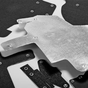
A typical removable separator cover combines an inner liner, flexible insulation core and outer protective layer. Thread, closures and reinforcement are selected as part of the complete construction.
The liner faces the separator surface. Depending on contact temperature and abrasion, options can include fiberglass, silica and other suitable high-temperature fabrics. Reinforcement may be added around nozzles, drain openings, panel corners and repeated-access areas.
Flexible fiberglass, silica and other high-temperature insulation materials are available. Core type and thickness depend on surface temperature, thermal objective, available clearance and acceptable panel weight. Different zones on a large separator can use different thicknesses when the application requires it.
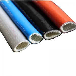
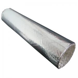
Outer materials can include silicone-coated fiberglass, PTFE-coated fabric, aluminized fabric and uncoated high-temperature textile. Selection is based on indoor or outdoor use, water, oil, chemical splash, cleaning practice, radiant heat and handling frequency.
D-ring straps, buckles, lacing hooks, wire, springs and hook-and-loop closures may be used where their exposure permits. Fasteners are placed where personnel can reach them without standing below a drain or reaching across an adjacent hot line.
Steam pressure alone should not be used to select the insulation. Provide the measured or calculated external surface temperature, normal operating condition, maximum upset condition and ambient environment. Startup conditions and intermittent service may also affect the required materials.
If a target outer-surface temperature or heat-loss value is required, include vessel dimensions, insulation thickness limits, ambient temperature and airflow. Thermal performance should be assessed for the complete installed cover, including seams, collars and unavoidable openings.
Separators may include pressure gauges, temperature sensors, nameplates, lifting lugs, vents, relief connections, inspection plugs or removable covers. The equipment owner should identify which items must remain exposed and which can sit beneath an access flap.
Instruments that require ventilation, calibration, observation or immediate operation should not be enclosed without approval. A clear window in the insulation is not a substitute for suitable instrument access and temperature limits.
Indoor steam plants mainly require resistance to handling, oil mist and normal mechanical-room conditions. Outdoor separators also face rain, wind, ultraviolet exposure and possible water entry at the upper seams. Panel overlaps, closure orientation and bottom drainage should be planned for the actual mounting position.
Coated fabrics can improve resistance to weather, but a sewn cover should not automatically be described as permanently waterproof. If the separator is exposed to washdown, sea spray or process chemicals, provide the substances and cleaning method during quotation.
A separator jacket can conceal flange, drain or instrument leakage if inspection access is ignored. Separate collars and removable lower panels can support routine checks. The equipment should be inspected before the cover is installed and after every maintenance activity.
If steam or condensate enters the jacket, remove the affected panels when site conditions allow and evaluate the liner, core, stitching and fasteners. Wet insulation should not be placed back over an active leak. Repair and verify the equipment first.
A fabrication drawing is the preferred reference. If a drawing is unavailable, provide measurements from fixed datums and photographs showing the complete separator from several directions.
For multiple separators of the same nominal size, confirm that nozzle and instrument positions are identical. Field changes can require different panel patterns even when equipment nameplates show the same model.
Large jacket sets can be supplied with position labels and a simple panel map. Labels can include the equipment number, upper or lower position, orientation and installation sequence. Customer part numbers and drawing revisions may also be added.
Remove only the panels needed for the planned service when practical. Place them on a clean, dry surface and retain the identification sequence. Inspect for cuts, abrasion, scorching, wet insulation, oil or chemical contamination, compressed core and damaged closures.
Before reinstalling the jacket, confirm that flanges, drains, trap connections and instruments are assembled correctly and free from leakage. Do not force panels over new tubing or modified fittings. Updated dimensions are required when the separator arrangement has changed.
The removable jacket is an external passive insulation product. It is not a pressure-retaining component, separator internal, steam trap, drainage device, leak-containment system, fire barrier or equipment guard. It must not obstruct relief connections, vents, drains, operating handles, inspection plates or required labels.
Insulation cannot compensate for incorrect separator selection, poor piping layout or failed condensate removal. The equipment owner and responsible engineer remain responsible for steam-system design, pressure safety, drainage, inspection and approval of the installed insulation.
BSTFLEX manufactures single replacement covers, complete separator jacket sets and repeat orders for steam-equipment suppliers, insulation contractors and industrial plants. Designs can be produced from approved drawings, field measurement sheets, templates or physical samples.
Project options include numbered panels, customer part numbers, equipment tags, drawing revision references, inspection records and individual packaging. For repeat production, any change to nozzles, instruments, supports or drain stations should be reported before release.
It is a custom removable thermal cover fitted around the external surface of a steam separator. It reduces exposed hot area while preserving access to drains, trap connections, instruments and inspection points.
The jacket can reduce heat transfer from the separator body, but it does not create the separation action. Moisture-removal performance depends on equipment selection, flow conditions, installation and effective condensate drainage.
Yes. The bottom panel can terminate around the drain, use a reinforced opening or connect to separate small covers. The full drain-station layout is required for correct design.
Yes. Panel divisions are developed for the actual orientation, head shape, nozzles, supports and available access space.
They can be included in the separator jacket, insulated with separate flange covers or left outside the main assembly. The choice depends on inspection requirements and adjoining pipe insulation.
Yes. Cutouts and fitted collars can keep them visible and operable. Provide their positions, projections and required tool clearances.
Weather-resistant fabrics and suitable overlaps can be selected, but seams and penetrations mean the assembly should not automatically be considered permanently waterproof. Outdoor drainage and exposure must be reviewed.
Yes, when the old jacket and current separator configuration are available for review. If the old cover has stretched or the drain and instruments have changed, new measurements should be supplied.
Send the separator drawing or dimensions, photographs, surface temperature, drain and trap layout, environment, required access points and quantity.
Send your steam moisture separator drawing, marked photographs, operating conditions and quantity to BSTFLEX. We will review panel divisions, drainage access, material construction and fastening positions before quotation.
Email: sales@pkfiresleeve.com
If you have questions or suggestions, please leave us a message,we will reply you as soon as we can!

 français
 Deutsch
 русский
 italiano
 español
 português
 Nederlands
 العربية
 日本語
日本語 한국의
한국의 Türkçe
 Polski
 Tiếng Việt
 slovenský
 Indonesia