order(moq):
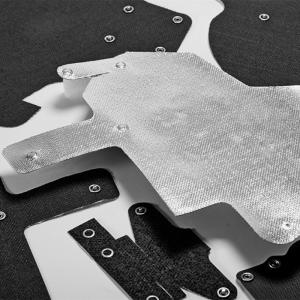
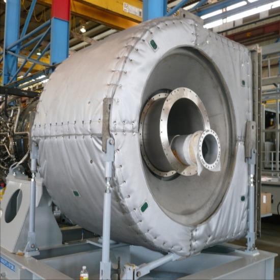
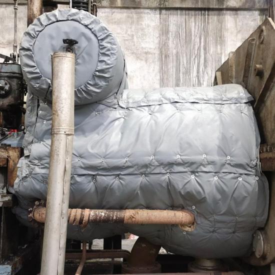
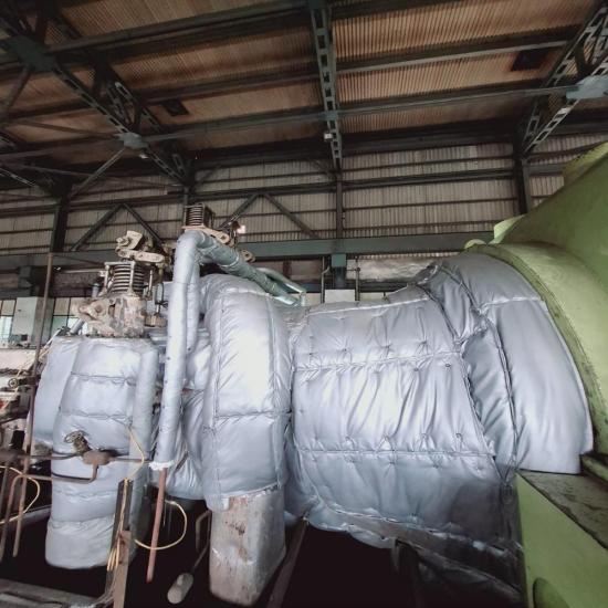
1A removable turbine insulation blanket is a shaped, reusable thermal insulation section manufactured for approved external surfaces on an industrial turbine system. Unlike a loose insulation sheet, each section is patterned for a defined location and identified so it can be removed during an outage and returned to the correct position.
BSTFLEX manufactures turbine blankets from equipment drawings, site dimensions, templates, three-dimensional measurement data or approved samples. The blanket map follows the turbine maintenance plan, dividing the insulation around casing joints, valve chests, flanges, piping, instruments and inspection points.
This product is intended for industrial turbines and power-generation equipment. It is not an automotive turbocharger blanket and should not be specified using automotive turbo blanket dimensions or constructions.
Steam turbine casings contain split lines, bolted joints, valve chests, steam connections, drains and instrumentation. The insulation system must follow these shapes while leaving the correct points accessible for inspection, tightening and maintenance.
Large casing areas are normally divided into manageable blanket sections. Separate blankets can be used around valve chests, horizontal joints, flanges and steam piping. Section edges may be arranged to stagger seams where the project uses more than one insulation layer.
Gas turbine projects can include approved external casing surfaces, hot connections, exhaust transitions and associated piping. The insulation boundary must be defined by the turbine manufacturer, project engineer or approved drawing.
Compressor inlets, cooling-air paths, ventilation openings, combustion-system access, bearing housings, rotating parts and other functional areas must not be covered unless the equipment design specifically permits it. The blanket pattern must also account for thermal growth, vibration and maintenance clearances.
A turbine insulation system may contain many individual sections. Permanent identification is essential because similar-looking blankets can have different cut-outs, thicknesses and installation positions.
Blanket size and weight should remain practical for the available lifting and installation method. Large surfaces can be divided along casing joints, access routes and natural equipment boundaries.
| Component | Typical Options | Design Considerations |
|---|---|---|
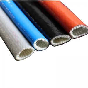
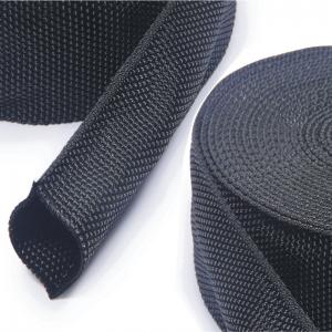
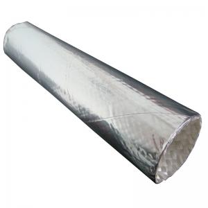
| Outer protective layer | Silicone coated fiberglass, PTFE coated fiberglass, aluminized fiberglass or other specified heat-resistant fabrics | Oil mist, moisture, abrasion, vibration, weather and handling during outages |
| Insulation core | Fiberglass needle mat, silica needle mat, ceramic fiber insulation or aerogel-based insulation | Operating temperature, required thermal result, available thickness and blanket weight |
| Hot-face liner | Silica fabric, fiberglass fabric, stainless steel foil or stainless steel mesh | Surface temperature, vibration, abrasion and contact with casing geometry |
| Fastening system | Stainless steel hooks, springs, lacing wire, buckles, D-rings or project-specified closures | Temperature, vibration, access, installation sequence and removal frequency |
| Reinforcement and support | Stainless steel mesh, quilting pins, support tabs, reinforced seams and local wear layers | Vertical surfaces, overhead sections, large blanket areas and repeated handling |
A material data-sheet temperature is not the rating of the complete turbine blanket. The liner, insulation core, outer cover, thread, fasteners, blanket thickness, surface contact and surrounding environment must be considered together.
A single removable layer may be suitable for some equipment surfaces. Other turbine projects use inner and outer blanket layers with staggered seams to reduce direct heat paths and improve coverage around complex joints. The number of layers and total thickness must be determined from the project specification and thermal requirements.
When multiple layers are used, each inner blanket should be identified with the corresponding outer blanket. The installation map must show the correct sequence so outer panels are not fitted over missing or incorrectly positioned inner sections.
Separate covers are normally preferable for valves, flanges and pipe sections that require independent maintenance. This allows one component to be opened without disturbing a large section of turbine-casing insulation.
For an existing turbine, photographs alone are not normally sufficient for a complete blanket set. Use drawings, templates, detailed measurements, digital scanning data or an approved sample system to define the geometry and location of every section.
Replacement projects should begin with a blanket inventory. Record the identification number, installation position, dimensions, condition and reason for replacement. Missing labels, compressed insulation, torn liners, failed fasteners and oil contamination should be documented before the old system is removed.
An old blanket should not be copied without checking its fit. Repeated handling, heat exposure and previous repairs may have changed the dimensions. If the original blanket left gaps or interfered with access, the replacement pattern should be corrected from the equipment rather than duplicated exactly.
Turbine blankets can experience vibration and dimensional movement during start-up, operation and shutdown. Closures must retain the blanket without placing rigid restraints across moving joints or required clearances. Local reinforcement may be added around hooks, cut-outs and contact areas.
The blanket layout must allow for specified thermal expansion and should not bridge components that move independently. Expansion data and movement boundaries must come from the turbine documentation or project engineer.
Insulation should not be installed over active oil or steam leakage. Oil-contaminated insulation can create additional fire and maintenance risks and must be handled according to the facility procedure. Outer fabrics can be selected for resistance to the expected environment, but a coated fabric does not correct a leaking component.
Drainage paths and leak-detection areas should remain visible where required. Seams and overlaps should not direct leaking liquid into the insulation core or toward electrical and rotating equipment.
Visible blanket surfaces, seams and fasteners should be checked according to the plant inspection plan. Look for loose sections, missing hooks, damaged labels, staining, wet areas, displaced insulation and contact with moving or vibrating components.
After removal, store blankets in a clean, dry and identified condition. Avoid sharp folding or stacking heavy items on the insulation. Before reinstallation, confirm that the liner, core, outer cover and closures remain suitable for service.
BSTFLEX supports prototype sections, partial replacement sets and complete turbine blanket projects. Manufacturing information can be developed from approved drawings, dimensional records, templates, digital data or physical samples. Project documentation can include a blanket schedule, section labels, packing lists and installation references.
For shutdown projects, identify the required delivery sequence and outage date when requesting a quotation. Large systems may need phased measurement, sample approval and production so critical sections are available in the order required for installation.
No. This product is a modular insulation system for industrial steam and gas turbines. Automotive turbocharger blankets have different equipment geometry, construction and application requirements.
Large turbine systems normally require multiple numbered sections. Modular blankets are easier to handle and allow access to individual joints, valves and inspection points.
Only when the turbine documentation or responsible engineer specifically permits it. Bearing housings, lubrication interfaces, cooling paths and monitoring points often require defined clearances and should not be covered automatically.
Yes. The old sections, installation map and turbine dimensions should be checked before production. Any fit, access, contamination or labelling problem should be identified so it can be corrected.
Yes. Each section can carry a permanent part number, equipment reference, position, direction and layer designation according to the project schedule.
Outdoor constructions can be reviewed using appropriate outer fabrics, protected seams and drainage-aware layouts. Weather resistance depends on the complete assembly and installation, not only the outer fabric.
Send the turbine type, model, approved insulation boundary, drawings, temperature data, blanket schedule, quantity and outage requirements to BSTFLEX. We will review the section layout, materials, fasteners, identification and manufacturing plan for your project.
Email: sales@pkfiresleeve.com
If you have questions or suggestions, please leave us a message,we will reply you as soon as we can!

 français
 Deutsch
 русский
 italiano
 español
 português
 Nederlands
 العربية
 日本語
日本語 한국의
한국의 Türkçe
 Polski
 Tiếng Việt
 slovenský
 Indonesia